ADP5041
Data Sheet
Rev. 0 | Page 16 of 40
CH1
CH2
CH3
A CH3 4.48V
SW
V
OUT
V
IN
3.0V/DIV
20.0mV/DIV
1M&
B
W
20.0M
1.0V/DIV
B
W
400M
B
W
20.0M
200祍/DIV
1.0MS/s
1.0祍/pt
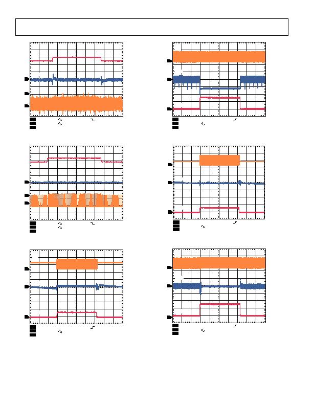
Figure 45. Buck Response to Line Transient, Input Voltage from 4.5 V to
5.0 V, VOUT1 = 1.8 V, PWM Mode
CH1
CH2
CH3
A CH3 4.48V
SW
V
OUT
V
IN
3.0V/DIV
50.0mV/DIV
1M&
B
W
20.0M
1.0V/DIV
B
W
20.0M
B
W
20.0M
200祍/DIV
1.0MS/s
1.0祍/pt
Figure 46. Buck Response to Line Transient, Input Voltage from 4.5 V to
5.0 V, VOUT1 = 1.2 V, PWM Mode
CH1
CH2
CH3
A CH3 150mA
V
OUT
SW
4.0V/DIV
100mV/DIV
1M&
B
W
20.0M
1M&
B
W
20.0M
300mA/DIV
B
W
20.0M
500祍/DIV
20.0MS/s
50.0ns/pt
I
OUT
Figure 47. Buck Response to Load Transient, I
OUT1
= 20 mA to 200 mA,
V
OUT1
= 3.3 V, Auto Mode
CH1
CH2
CH3
A CH3 150mA
V
OUT
SW
4.0V/DIV
100mV/DIV
1M&
B
W
20.0M
1M&
B
W
20.0M
300mA/DIV
B
W
20.0M
500祍/DIV
20.0MS/s
50.0ns/pt
I
OUT
Figure 48. Buck Response to Load Transient, IOUT1 = 50 mA to 500 mA,
VOUT1 = 3.3 V, Auto Mode
CH1
CH2
CH3
A CH3 150mA
V
OUT
SW
4.0V/DIV
100mV/DIV
1M&
B
W
20.0M
1M&
B
W
20.0M
300mA/DIV
B
W
20.0M
500祍/DIV
20.0MS/s
50.0ns/pt
I
OUT
Figure 49. Buck Response to Load Transient, IOUT1 = 20 mA to 200 mA,
VOUT1 = 1.8 V, Auto Mode
CH1
CH2
CH3
A CH3 150mA
V
OUT
SW
4.0V/DIV
100mV/DIV
1M&
B
W
20.0M
1M&
B
W
20.0M
300mA/DIV
B
W
20.0M
500祍/DIV
20.0MS/s
50.0ns/pt
I
OUT
Figure 50. Buck Response to Load Transient, IOUT1 = 50 mA to 500 mA,
VOUT1 = 1.8 V, Auto Mode
发布紧急采购,3分钟左右您将得到回复。
相关PDF资料
ADP5042ACPZ-2-R7
IC REG TRPL BCK/LINEAR 20LFCSP
ADT6402SRJZ-RL7
IC TEMP SENS TRIP PT PP SOT-23-6
ADT6501SRJZP085RL7
IC TEMP SENSOR MICROPWR SOT23-5
ADT7302ARTZ-500RL7
IC SENSOR TEMP 13BIT DGT SOT23-6
ADT7310TRZ
IC TEMP SENSOR 16BIT SPI 8SOIC
ADT7461AARMZ-R
IC TEMP SENSOR DGTL 2CH 8-MSOP
ADT7461ARMZ-2R
IC TEMP SENSOR DGTL 2CH 8-MSOP
ADT7463ARQZ-REEL
IC REMOTE THERMAL CTRLR 24-QSOP
相关代理商/技术参数
ADP5041CP-1-EVALZ
功能描述:ADP5041 - DC/DC, Step Down with LDO 3, Non-Isolated Outputs Evaluation Board 制造商:analog devices inc. 系列:- 零件状态:有效 主要用途:DC/DC,LDO 步降 输出和类型:3,非隔离 功率 - 输出:- 电压 - 输出:- 电流 - 输出:1.2A,300mA,300mA 电压 - 输入:2.3 V ~ 5.5 V 稳压器拓扑:降压 频率 - 开关:3MHz 板类型:完全填充 所含物品:板 使用的 IC/零件:ADP5041 标准包装:1
ADP5042
制造商:AD 制造商全称:Analog Devices 功能描述:Micro PMU with 0.8 A Buck, Two 300 mA LDOs Supervisory, Watchdog and Manual Reset
ADP5042ACPZ-1
制造商:Analog Devices 功能描述:PMU 2 LDO DUAL BUCK 20LFCSP 制造商:Analog Devices 功能描述:PMU, 2 LDO, DUAL BUCK, 20LFCSP
ADP5042ACPZ-1-R7
功能描述:IC REG TRPL BCK/LINEAR 20LFCSP RoHS:是 类别:集成电路 (IC) >> PMIC - 稳压器 - 线性 + 切换式 系列:- 标准包装:2,500 系列:- 拓扑:降压(降压)同步(3),线性(LDO)(2) 功能:任何功能 输出数:5 频率 - 开关:300kHz 电压/电流 - 输出 1:控制器 电压/电流 - 输出 2:控制器 电压/电流 - 输出 3:控制器 带 LED 驱动器:无 带监控器:无 带序列发生器:是 电源电压:5.6 V ~ 24 V 工作温度:-40°C ~ 85°C 安装类型:* 封装/外壳:* 供应商设备封装:* 包装:*
ADP5042ACPZ-2
制造商:Analog Devices 功能描述:PMU 2 LDO DUAL BUCK 20LFCSP 制造商:Analog Devices 功能描述:PMU, 2 LDO, DUAL BUCK, 20LFCSP
ADP5042ACPZ-2-R7
功能描述:IC REG TRPL BCK/LINEAR 20LFCSP RoHS:是 类别:集成电路 (IC) >> PMIC - 稳压器 - 线性 + 切换式 系列:- 标准包装:2,500 系列:- 拓扑:降压(降压)同步(3),线性(LDO)(2) 功能:任何功能 输出数:5 频率 - 开关:300kHz 电压/电流 - 输出 1:控制器 电压/电流 - 输出 2:控制器 电压/电流 - 输出 3:控制器 带 LED 驱动器:无 带监控器:无 带序列发生器:是 电源电压:5.6 V ~ 24 V 工作温度:-40°C ~ 85°C 安装类型:* 封装/外壳:* 供应商设备封装:* 包装:*
ADP5042CP-1-EVALZ
功能描述:电源管理IC开发工具 Output Buck Regulator + Dual Fixed Eval RoHS:否 制造商:Maxim Integrated 产品:Evaluation Kits 类型:Battery Management 工具用于评估:MAX17710GB 输入电压: 输出电压:1.8 V
ADP5042CP-2-EVALZ
功能描述:电源管理IC开发工具 Output Buck Regulator + Dual Fixed Eval RoHS:否 制造商:Maxim Integrated 产品:Evaluation Kits 类型:Battery Management 工具用于评估:MAX17710GB 输入电压: 输出电压:1.8 V